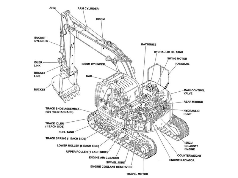
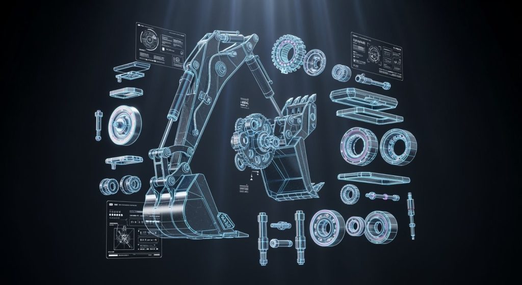
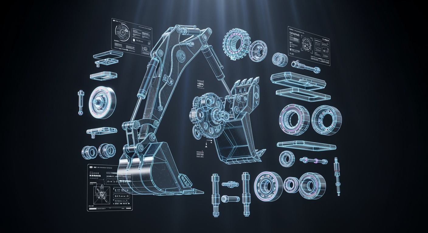
An excavator assy combines mechanical, hydraulic, or structural pieces into a single working unit. You depend on an assy for excavator parts to maintain steady machine operation every single day. Detailed component diagrams and schematics help you identify worn components quickly. These clear system schematics also speed up failure troubleshooting and prevent costly job site downtime. You can rely on this complete guide to navigate complex machine structures effectively. A proper guide directs your search for accurate replacements without any guessing. Understanding every excavator parts diagram simplifies routine maintenance and complex repairs. Work much faster by mastering these essential excavator components today.
Key Takeaways
Excavator diagrams help you find worn parts fast and avoid expensive delays at the work site.
Clean bottom setups and correctly tightened track chains defend lower frame parts from wearing out too soon.
Check and adjust your undercarriage track tightness every 100 to 150 hours to keep parts aligned correctly.
Changing your engine oil regularly and using clean fuel filters will help your diesel engine run smoothly.
Checking your hoses every day helps you find small surface cracks early and stops sudden fluid leaks.
Ground engaging tools like bucket teeth protect the main bucket frame from hard ground impacts.
Always use your machine’s serial number to order correct replacement parts without making expensive mistakes.
Complete Guide to Machine Architecture and Excavator Components
You learn complete machine architecture by studying basic machine layouts. This complete guide to components helps you understand structural foundations clearly. Heavy machinery relies on durable sub-assemblies to complete tough digging work.
You can inspect different types of excavators to see how structural builds vary across job sites.
Excavator Type | Key Structural Feature |
|---|---|
Crawler Excavator | Built with tracks (continuous belts). |
Wheeled Excavator | Built with rubber tires (wheels). |
Primary Mechanical Structure
Lower Undercarriage Base Frame
You rely on the undercarriage base frame to support heavy machinery operations. This rigid lower structure bears the full weight of your machine during heavy lifting tasks. The sturdy undercarriage transfers operational loads directly into the ground surface.
You maintain steel track frames and support structures on this lower base frame. Clean dirt out of these lower components regularly to prevent premature wear. Clean base assemblies protect track chains and bottom rollers from abrasive debris accumulation.
Upper Rotating House Frame
You control machine rotation on the upper rotating house frame assembly. This upper frame supports your engine module, main hydraulic pumps, and operator cab securely. Strong structural steel plates absorb extreme torque forces during fast swinging movements.
You access major internal engine parts of an excavator through this upper house platform. Proper weight distribution across this upper structure protects internal hydraulic lines during continuous operations. Robust upper frame structures keep vital components safe from external job site impacts.
Main Interface Assemblies
Center Swivel Joint Assembly
You route pressurized fluid through the center swivel joint assembly during travel operations. This mechanical rotary manifold connects your upper rotating frame to your lower undercarriage smoothly. High-pressure hydraulic oil flows continuously while your upper house rotates full circles.
You prevent fluid leaks by maintaining inner rotary seals inside the swivel manifold. Damaged center joint seals reduce travel motor power on both track sides. Regular seal maintenance extends the service life of major excavator components.
Front Attachment Mounting Pins
You secure working attachments to your boom arm using heavy-duty mounting steel pins. These hardened steel pins hold work tools tight during heavy rock digging tasks. Quality mounting hardware prevents excessive play between main components of an excavator arm.
You grease these mounting pins daily to reduce metal surface friction effectively. Worn attachment pins cause slop and misalign various excavator attachments during precise grading work. Replacing worn bushings early protects expensive parts of an excavator from structural damage.
Key Parts of an Excavator: Undercarriage Assy
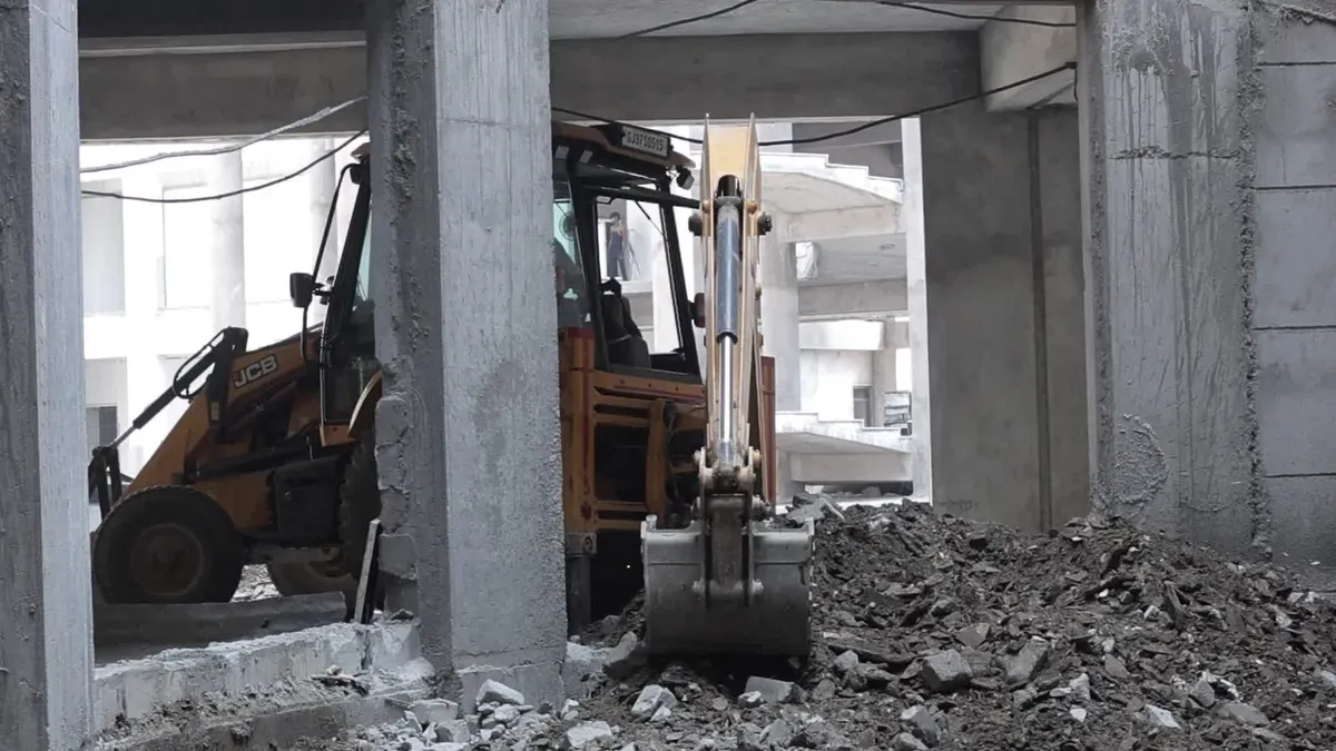
Check major parts of an excavator to keep your machine active. The lower frame holds total machine weight during daily job site tasks. Good care protects undercarriage components from wearing out too early. This complete guide details important lower frame maintenance steps.
Track Group Assembly
Track Chain Assembly and Shoes
Track units grip ground surfaces to move heavy machinery across sites. Tough track shoes bolt tightly onto continuous track chain links. Correctly adjusting undercarriage tracks stops loose sag and preserves straight alignment.
Wrong track chain tension shortens the useful working life of undercarriage components. Overly tight tracks raise friction levels between track chains and rollers. High friction quickly wears out links, top carrier rollers, and rubber seals. Track chain failure happens when link stretch goes over two percent or when link plates crack.
Idler Wheel and Recoil Spring
The front undercarriage idler wheel guides track units while keeping them aligned. A strong recoil spring takes hard front impacts on rough ground. Shock absorption guards internal drive components and attached parts against severe damage.
Leaking seals cause track adjuster problems over long working periods. You should fix track tension every 100-150 hours depending on ground conditions. Regular checks stop steel tracks from popping off the front idler wheel.
Roller Component Groups
Upper Carrier Rollers
Upper carrier rollers hold up top heavy track weight during travel. These sturdy roller components keep steel chains from sagging downward. Smooth roller rotation lowers drag forces and improves full machine performance.
Top roller breakdowns happen because of broken seals or bad bearings. These problems create flat spots and deep wear grooves on metal surfaces. You need to inspect these parts of an excavator every 250 hours for early damage.
Lower Track Rollers
Lower track rollers carry total machine weight across moving steel track links. These bottom rollers keep heavy tracks turning smoothly during work. High-quality seals keep internal bearings safe from thick mud and grit.
Maintenance Task | Recommended Interval (Operating Hours) |
|---|---|
Track Tension Adjustment | Every 100-150 hours |
Roller Lubrication Check | Every 200 hours |
General Roller Inspection | Every 250 hours |
Alignment Issue Check | Every 200-300 hours |
Excavator undercarriage systems need organized care every single day. Do a complete roller lubrication check after every 200 operating hours. Inspect alignment issues every 200-300 hours to maintain optimal digging output.
Final Drive Motor Assembly
Travel Hydraulic Motor
The travel hydraulic motor turns fluid pressure into steady rotary power. High-pressure hydraulic oil pushes internal motor pistons to turn the drive shaft. This generated force helps your heavy undercarriage climb steep ground easily.
Internal motor leaks drop travel speed on one track side. Your excavator then pulls toward one direction while moving across jobs. Installing fresh internal seals restores equal hydraulic pressure for straight travel.
Planetary Gear Reduction Unit
The planetary gear reduction unit boosts torque sent to heavy track sprockets. Multi-stage gear sets multiply power to turn thick steel tracks easily. Mechanics check key parts often to stop severe internal machine damage.
Worn gear teeth cause extra loose movement and make loud clunking sounds when shifting directions. Hot drive housings and grinding noises mean severe bearing failure inside planetary gear sets. This guide helps you spot broken parts of an excavator before complete gearbox failure happens.
Excavator Engine Assembly and Upper House Layout
Your excavator needs strong engine and power parts to handle tough daily work. The complete diesel engine unit feeds mechanical power right into main hydraulic parts and cooling units.
Excavator Engine Assembly Systems
Complete Diesel Engine Unit
You rely on the main engine to create steady mechanical power for your machine. This unit burns diesel fuel and keeps the main drive shaft turning smoothly.
Performance Metric | Quantitative Value | Supporting Context |
|---|---|---|
Horsepower (Power Output) | 110 to 150 kilowatts | Standard requirement for a 20-ton excavator to drive its main hydraulic pumps. |
Fuel Efficiency Improvement | Up to 12% reduction in fuel waste | Achievable under heavy loads by engines using advanced high-pressure common rail systems. |
A healthy engine helps your machine run better on busy job sites. Regular oil changes protect internal cylinder walls during long work periods.
Turbocharger and Fuel Injection
The turbocharger pushes extra compressed air right into the engine cylinders. High-pressure injection valves spray fine fuel mist for clean, strong burning. This precise fuel delivery improves engine power while cutting harmful exhaust smoke.
Dirty fuel filters stop essential fluid from reaching your machine engine. You should swap out bad fuel parts fast to prevent sudden engine stalls.
Main Hydraulic Pump Assembly
Variable Displacement Axial Pumps
Variable displacement axial pumps change mechanical engine power into hydraulic fluid power. Inside the pump, small pistons slide back and forth to push oil through hydraulic lines. You can change oil flow instantly when digging work gets much harder.
Worn swashplates lower hydraulic oil pressure when lifting heavy objects. Checking internal pump parts often prevents sudden power loss during tough jobs.
Pilot Regulator Control Valve
The pilot regulator valve directs hydraulic oil flow to main machine controls. Small pilot pressure signals shift large spool valves without any jerky movements. This steady oil pressure helps your machine move attached tools with great care.
Dirty hydraulic fluid clogs small control valve passages after heavy use. Fresh oil keeps your control levers reacting fast during delicate digging work.
Swing Drive Mechanism
Swing Hydraulic Motor and Brake
The swing hydraulic motor turns the upper house around in full circles. A built-in mechanical brake keeps the upper house safely frozen on steep hills. You set this internal parking brake whenever you stop spinning the cab.
Worn motor seals leak hydraulic fluid and lower overall stopping power. Swapping out bad brake parts keeps your machine safe on sloped ground.
Planetary Swing Reduction Gearbox
The planetary swing gearbox multiplies the rotating power coming from the motor. Multi-stage gears lower turning speed while raising total rotating force. These strong mechanical parts turn the large slewing ring gear smoothly on your machine.
Low gear oil creates intense heat and heavy friction inside the gearbox. You must check oil levels often to stop gear teeth from snapping off.
Front-End Working Group Assembly
You manage front excavator tools to perform tough digging and loading work. Front attachments operate together to supply high machine output on active job sites.
Boom Assembly Group
Boom Weldment and Foot Pins
You count on the heavy boom structure to hold main lifting loads. Strong foot pins fasten the main boom right onto the upper rotating frame unit.
Forged steel foot pins absorb hard structural force during heavy digging work. Good pin greasing stops early surface scratches on pivot parts.
Dual Boom Hydraulic Cylinders
Two hydraulic cylinders lift the main boom up using strong hydraulic power. Even oil flow into both cylinders keeps straight lifting force across heavy attachments.
Leaking cylinder seals drop lifting power during heavy work. Swapping worn hydraulic seals brings back best operating safety fast.
Arm and Stick Assembly
Arm Hydraulic Cylinder
The arm hydraulic cylinder drives the inward pull force of the stick group. You move the stick position to stretch reach and control digging depth well. Boom and arm lengths directly set excavator digging limits during daily work.
Arm Type | Arm Length | Maximum Digging Depth | Maximum Dump Height |
|---|---|---|---|
Standard Arm | 3 ft 9 in (1.15 m) | 7 ft 6 in (2280 mm) | 8 ft 6 in (2580 mm) |
Long Arm | 4 ft 5 in (1.35 m) | 8 ft 2 in (2480 mm) | 8 ft 10 in (2700 mm) |
Longer arm choices add overall reach while boosting total digging depth. Choosing right attachments boosts digging speed across different ground types.
Connecting Bucket Linkage
Connecting linkage moves mechanical force from the arm cylinder to different tools. This linkage unit swings tools smoothly through full motion curves.
Worn joint pins create loose play and tilt different working tools. Checking pivot bushings often stops early part wear.
Bucket and GET Assembly
Bucket Cylinder Assembly
The bucket cylinder turns the tool to dig, scoop, and dump dirt quickly. High oil pressure powers exact bucket curling movements during earthwork.
Clean hydraulic oil lets inner cylinder valves work smoothly. Right care guards important parts of an excavator against inner pressure loss.
Bucket Teeth and Adapters
Ground engaging tools break hard dirt and guard main excavator buckets against bad wear. You fit special tooth metals to boost digging work in tough ground types.
Material Type | Optimal For | Key Property | Dominant Wear Condition |
|---|---|---|---|
Through-Hardened Steel | High-impact material, mixed ground | Overall toughness | Impact-dominated wear |
Cast Alloy | Clean abrasive material, sand, gravel | Maximum surface hardness | Pure abrasion |
A worn adapter makes teeth fit loosely, speeding up tooth damage. Regular tooth life changes based on ground wear levels:
Sand, Gravel: 150–300 hours
Compacted Gravel, Caliche: 80–150 hours
Hard Rock: 40–100 hours
Highly Abrasive Ore: 20–60 hours
Keeping good adapter shape gives maximum working life for your bucket parts. Using this guide helps you swap worn parts of an excavator before big breakages occur. Follow this guide to handle key bucket tools and heavy excavator components easily.
Hydraulic and Electrical Diagram Routing
Main Control Valve Assembly
Spool Valve Distribution Block
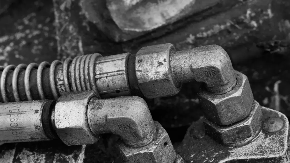
You look at this hydraulic system map to trace fluid lines through the main control valve assembly. This middle block gets high-pressure oil straight from the main pumps. Inside, sliding spools change positions to send fluid right to various cylinders and travel motors.
Smooth spool movements give you precise machine control during tricky digging tasks. Worn spools let oil leak past internal seals inside the block. This loss drops machine power and slows down tool reaction times.
Main Pressure Relief Valves
You protect heavy hydraulic components from dangerous pressure spikes using main relief valves. These spring-loaded safety valves open when internal pressure reaches unsafe limits. Extra oil flows straight back into the main hydraulic tank.
Wrong pressure settings lower overall lifting power during heavy digging tasks. You test relief valve settings during regular machine checkups. Clean oil keeps these critical safety valves working longer.
Fluid Power Lines
High-Pressure Hydraulic Hose Lines
You count on flexible high-pressure hoses to send fluid power across moving machine joints. Multi-layer rubber walls with steel wire withstand tough, constant pressure changes. These strong hoses bend easily during boom and arm movements.
Outer covers protect inner steel layers from rough job site scraping. You check flexible lines daily to find small surface cracks early. Replacing worn hoses prevents sudden fluid leaks and keeps hydraulics working safely.
Steel Hydraulic Piping
Steel tubes carry fluid along solid parts like the upper frame and main boom structure. Rigid steel lines move high oil volumes without swelling under heavy loads. Strong mounting brackets hold these steel tubes tight against the machine frame.
Vibration clamps hold steel piping safe from heavy engine shaking. Loose clamps cause metal fatigue and stress cracks along pipe bends over time. You tighten mounting hardware to keep steel pipes lined up correctly.
Cab Control Circuits
Pilot Control Joysticks
You control machine movements using low-pressure pilot joysticks inside the operator cab. Moving a lever sends small fluid signals straight to the main control valve. This easy-to-use system reduces operator tiredness during long work days.
Smooth pilot signals deliver exact fluid responses to working attachments. Sticky joystick valves cause jerky cylinder movements during precise grading jobs. Clean pilot oil keeps joysticks moving smoothly for best machine performance.
Wiring Harness and Controller
You monitor excavator systems through the main electronic controller and wire harness. This main unit processes sensor signals to adjust engine power and hydraulic flow automatically. Sealed wire connectors keep sensitive electrical pins safe from dirt and water.
Damaged wiring harnesses cause false error codes and disrupt electric pump controls. You check electrical harnesses during routine maintenance to spot pin rust early. Good electrical connections keep all excavator hydraulics running at peak efficiency.
Reading Diagram Schematics for Assy for Excavator Parts
Mechanics examine detailed sub-assembly blueprints to pinpoint damaged internal components accurately. These drawings show clear part numbers so you order correct replacements quickly. Following these technical schematics prevents long machine delays on job sites. This complete guide helps you read every hydraulic diagram easily.
Exploded View Diagrams
Part Callout Numbering Systems
Exploded view drawings show how small pieces fit into a full assy for excavator parts. Small numbers point directly to individual components within the mechanical diagram. You match these numbered callouts to the list beneath the drawing. Avoid common reading errors while reviewing your schematic.
Common Mistake | Typical Consequence | Recommended Solution |
|---|---|---|
Misreading Symbols or Flow Paths | Leads to incorrect assembly, causing equipment malfunction or failure. | Cross-reference each symbol with standard charts to verify its function and flow direction. |
Overcomplicating Diagrams | Makes troubleshooting and future design modifications significantly more difficult. | Utilize simplified, modular layouts that distinctly separate components and system functions. |
Ignoring Valve Positions and States | Can result in unintended pressure buildup or incorrect system operation. | Ensure all valve states are clearly indicated to provide a complete picture of system operation. |
Using Symbols Inconsistently | Causes miscommunication and errors during the assembly process. | Adhere to a single symbol standard throughout the diagram and clearly label which standard is used. |
Omitting Essential Components (e.g., reservoirs, filters, pilot lines) | Increases the risk of system contamination or improper hydraulic fluid control. | Verify that all critical components are included and accurately positioned within the system layout. |
Seal Kit and Hardware Groups
A standard excavator parts diagram groups tiny O-rings, backing rings, and bolts together. These complete hardware packs streamline your daily maintenance work. Swapping out whole seal packages stops minor fluid leaks before larger issues start.
ISO Hydraulic Schematics
ISO 1219 hydraulic drawings improve repair accuracy when diagnosing machine failure:
Universal Blueprint: ISO fluid drawings offer a clear visual layout of hydraulic lines, regardless of actual physical placement.
Systematic Diagnosis: Mechanics trace oil paths to find broken components by comparing real performance against the drawing.
Standardized Language: International rules standardize internal symbols to create a common language across heavy machinery types.
Diagnostic Roadmap: Schematics work like structural maps, helping technicians find precise problems without guessing.
Avoiding Errors: Learning standard symbols prevents wrong assumptions about circuit operations and stops costly mistakes.
Standard Valve and Pump Symbols
You need to identify standard symbols on hydraulic drawings:
Hydraulic Pump Symbol: A round shape with a solid arrow pointing out, showing fluid moving through system lines.
Hydraulic Motor Symbol: A circle with an inward arrow, showing high-pressure fluid turning internal motor parts.
Directional Control Valve Symbol: Several connected boxes that show fluid paths for different valve positions.
Pressure Valves: Drawn with small springs and arrows, like typical relief valve icons.
Adjustable Components: Identified by extra diagonal arrows drawn across the main valve symbol.
Circuit Pressure Test Points
Checking fluid pressure means attaching testing tools to special ports across the hydraulic system.
Test Point Location | Details |
|---|---|
Main Control Valve | A primary test point where hydraulic flow is directed to different functions (e.g., booms, arms, swing). |
Hydraulic Pump | A key location to test the output pressure and health of the main power source of the hydraulic system. |
Auxiliary Circuits | Used for testing pressure in circuits dedicated to attachments like hydraulic breakers, thumbs, or grapple buckets. |
Maintenance Sourcing Strategies
Identifying High-Wear Bushings
Routine checks stop sudden mechanical breakdowns during heavy digging jobs. You must inspect structural joints across front linkage assemblies and lower frames. Proper excavator parts care keeps high-wear bushings sliding smoothly under heavy working loads.
Cross-Referencing OEM Part Numbers
Follow these clear steps to cross-reference replacement parts without making mistakes:
Locate Machine Identification: Find the serial plate inside the operator cab and write down the full model number.
Retrieve OEM Part Number: Check official parts books or search online catalogs using your exact machine model.
Verify Compatibility: Match part numbers with supplier databases to confirm correct fitment before buying any items.
“Ordering by machine serial number rather than a memorized part number is the single biggest error-reduction step a procurement team can take,” notes a service bulletin practice common across major OEM parts networks.
Comparing price ranges and fitment choices helps you pick good parts of an excavator. Following standard care rules keeps your heavy equipment running reliably every day.
Part Type | Price Range (USD) | Performance & Fitment | Best For Application |
|---|---|---|---|
Genuine OEM | $50-$1,500+ | Exact fit, lab-tested to factory specifications | Critical engine & hydraulic components where precision is paramount |
Premium Aftermarket | 30-70% less than OEM | Often meets or exceeds OEM specifications | Wear parts like bushings, filters, and undercarriage components |
OEM Remanufactured | 40-70% of new OEM price | Restored to original OEM performance standards | Budget-sensitive operations or maintaining older machine models |
Budget Aftermarket | 10-50% less than premium aftermarket | May have inconsistencies in dimensions or quality | Non-critical applications or temporary repairs only |
This practical manual simplifies buying every required assy for excavator parts. Finding correct parts stops installation mistakes and keeps machines working much longer.
Learning component diagrams helps you find machine problems much faster. Clear system pictures let you spot broken mechanical parts right away. You avoid expensive repair mistakes and keep your excavator working hard on busy job sites.
Working with a trusted supplier gives you quick access to quality excavator parts. YNF Machinery sells strong replacement components that help with your long-term machine care. You prevent costly job delays by getting the right parts quickly for your heavy equipment fleet.
Keep updated diagram books nearby during daily work, and call YNF Machinery today for expert help finding parts.
FAQ
How often should you check undercarriage track tension?
You need to adjust track tension every 100 to 150 hours of work. Heavy ground conditions alter how fast tracks go loose. Regular checks keep track chains from slipping off the front idler wheel.
When should you inspect upper and lower track rollers?
You must complete roller grease checks every 200 hours of operation. Inspect upper and lower rollers every 250 hours. Proper oil guards inner bearings against thick mud and sharp grit.
What single step best reduces part ordering errors?
You stop buying mistakes by finding your machine serial number first. Look for the serial plate inside your operator cab. Matching exact serial numbers with component catalogs guarantees a great fit.
Why do center swivel joint seals require regular maintenance?
Inner rotary seals push high-pressure hydraulic oil through the swivel joint. Broken seals cause internal fluid leaks. These leaks drop hydraulic power in travel motors and stop straight travel.
What signs indicate planetary gear failure inside a travel drive?
Hot drive covers and harsh grinding noises show bearing failure in gear sets. Worn gear teeth make extra loose movement. You hear loud clunking sounds whenever you switch travel directions.
How long do bucket teeth last in hard rock conditions?
Bucket teeth usually last between 40 and 100 hours in hard rock. Tough ground conditions speed up outer wear. Swapping worn teeth early shields your main bucket structure from heavy damage.
What warranty coverage applies to replacement engine assemblies?
Important replacement engine assemblies include a warranty that lasts 3 to 6 months. Good warranties protect your parts purchases and keep heavy equipment working on busy job sites.