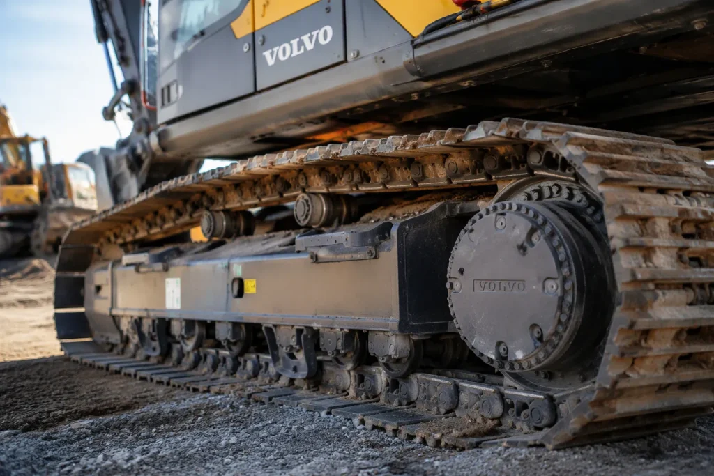
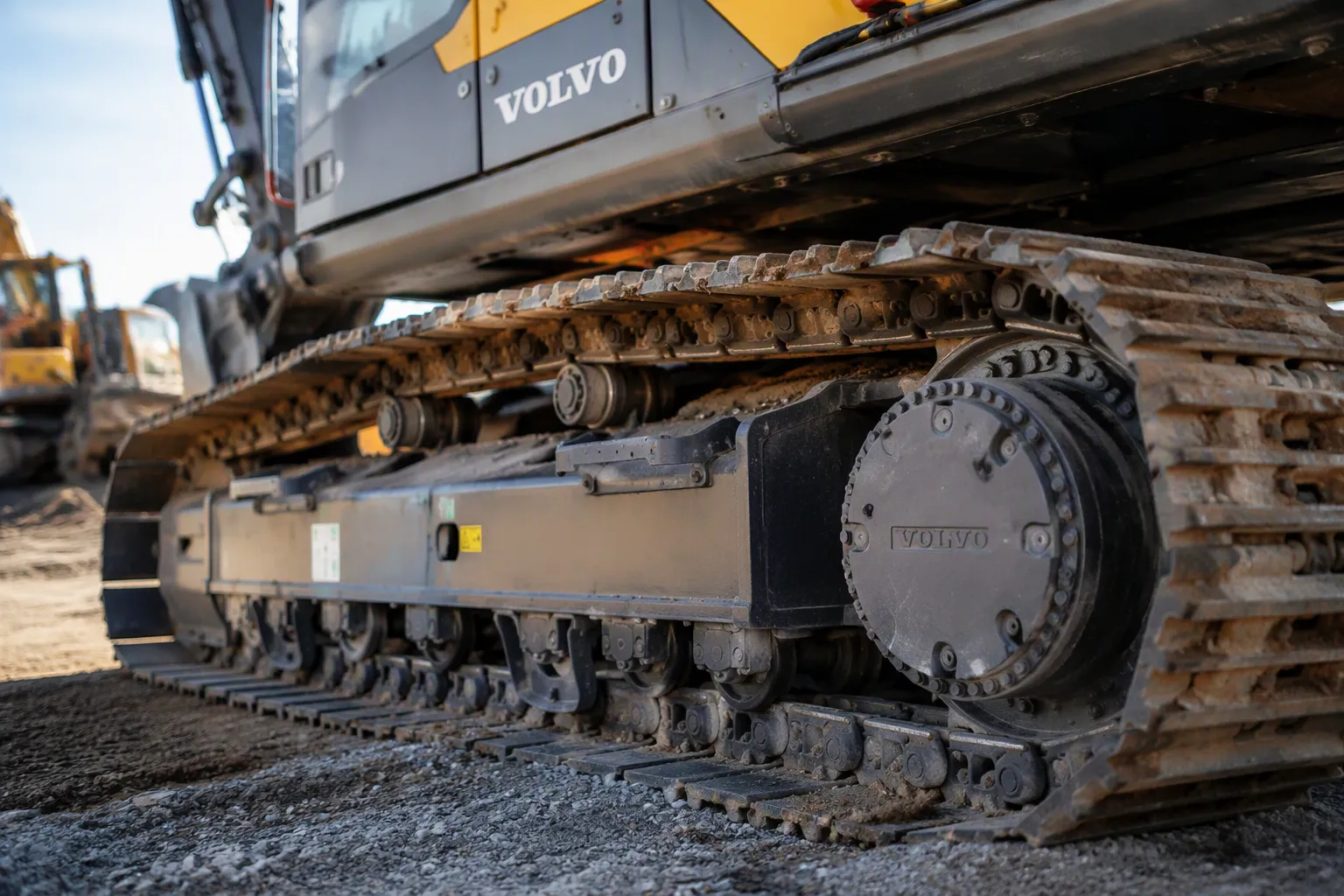
A tracked Volvo excavator undercarriage may include tracks, rollers, idlers, sprockets, a track frame and a tensioning arrangement. Steel chains, shoes, rubber tracks, pads and segmented sprockets depend on the actual machine design. The components work as a system; identify the installed arrangement before ordering or servicing parts.
Key Takeaways
The undercarriage works as one system. One worn part stresses the others.
Check your tracks often. Look for wear signs like sharp sprocket teeth or flat spots on bushings.
Set the right track tension. Loose tracks derail. Tight tracks overload the final drive.
Replace worn parts early. This prevents damage to other parts and saves money.
Follow safety rules. Release pressure and use secure support before you inspect.
Main Parts of an Excavator Undercarriage
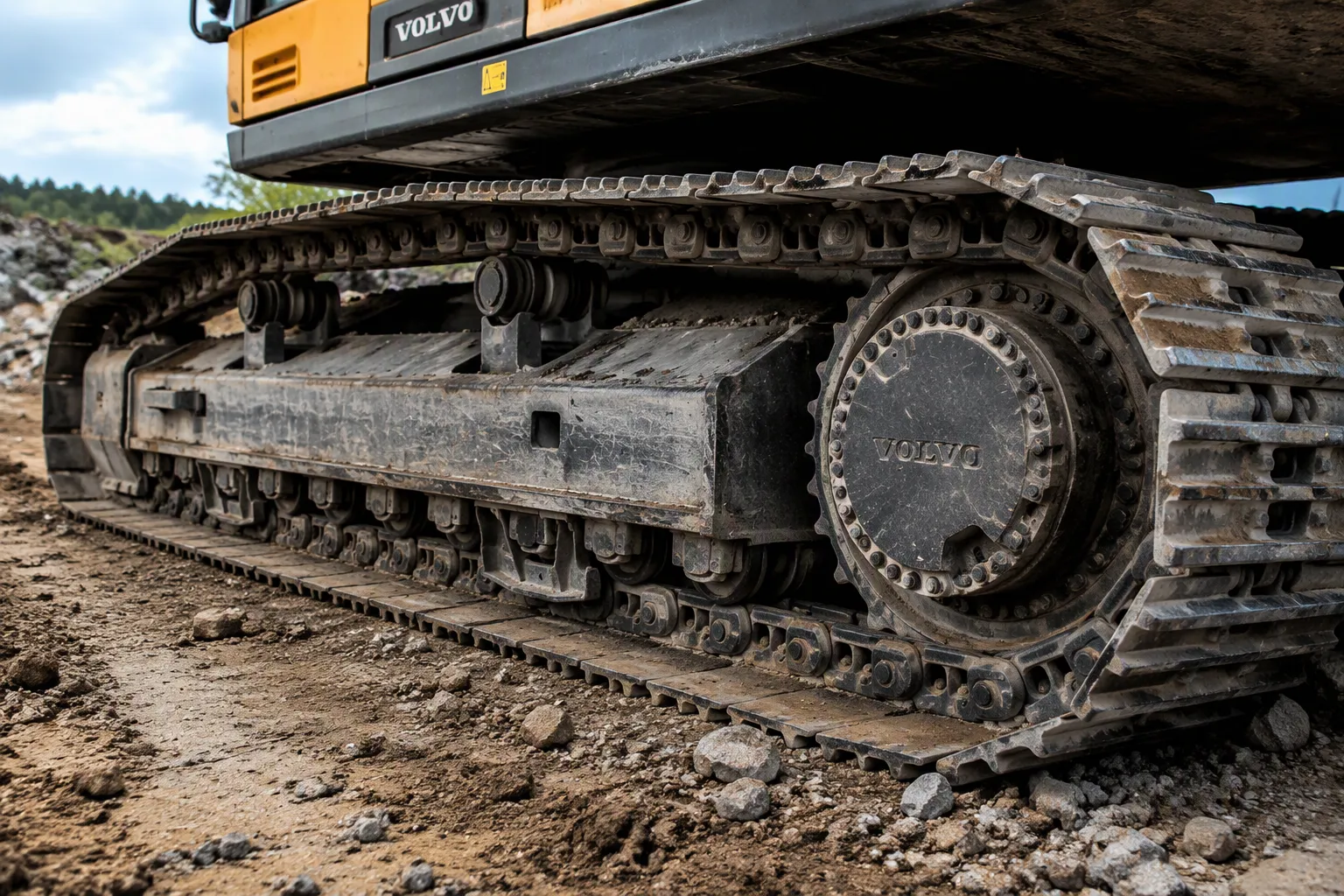
Group undercarriage parts by their support, guidance, traction and drive functions. Use the actual machine catalog to identify the assembly and relevant component specifications rather than assuming universal dimensions or testing claims.
Track Chains and Track Shoes
A track chain is a loop of linked steel that rolls under your machine. Each link holds a pin and a bushing. These let the chain bend as it wraps around the drive sprocket and guide wheel. Track shoes bolt onto the chain links. These flat plates touch the ground and carry the load.
Shoe width changes how your machine acts. Wider track shoes add more contact area. This lowers ground pressure and helps the machine float on soft ground like mud, clay, peat, and wet fill. Narrower or medium shoes work well on rock, quarry, or demolition sites. Too much width there can cause bending stress, edge damage, side load on pins and bushings, and turning resistance. Machine mass matters too. A mid-size excavator sends large forces through each side of the undercarriage. So match shoe width to soil conditions and final drive load. Check track pitch, bolt pattern, and roller clearance before you buy.
Rollers, Idlers, and Sprockets
Track rollers, often called bottom rollers, sit under the track frame. They support the machine’s weight as it moves. A worn roller shows clear warning signs. Watch for a roller shell that does not visibly turn when the track moves. Look for localized heat after short travel, fresh oil around a seal, or a flat or polished tread area. Listen for scraping or grinding noises. Check for repeated flange contact on one side. Greasy residue around the hub, squeaking, and uneven tread wear also point to seal failure or bearing seizure. These symptoms suggest a cause, but only inspection confirms it.
Idlers guide the track and sprockets transfer drive to it. Location and one-piece or segmented construction vary. Confirm the actual design and service procedure before planning replacement.
Aspect | Sprocket Segments | Replacing Entire Sprocket |
|---|---|---|
Replacement scope | Confirm the required segment replacement scope in the applicable service instructions | Confirm the required sprocket replacement scope in the applicable service instructions |
Hub, shaft, bearings, housing | Check which associated components require inspection or service | Do not assume every sprocket replacement requires internal final-drive disassembly |
Cost and downtime | Compare the actual parts and qualified installation quotation | Compare the actual parts and qualified installation quotation |
Protection of final drive | Inspect related drive and track components using their service limits | Inspect related drive and track components using their service limits |
Maintenance practice | Use the actual inspection schedule and measured service limits | Use the actual inspection schedule and measured service limits |
Do not apply a universal wear percentage or hourly interval to every sprocket or segment.
Inspect the sprocket, tracks and related components together. Obtain the required replacement scope from measured condition and the applicable service instructions.
Key Parts of the Undercarriage and Their Roles
You get a clearer picture when you group the key parts of the undercarriage by the job they do. Some parts carry weight. Other parts create motion. A few do both at once. This grouping helps you trace a problem back to its source instead of guessing.
Support and Stability Components
The track frame supports and locates undercarriage components. Bottom rollers support the track system and carrier rollers, where fitted, support its upper run. Idlers guide the track. The upper-machine counterweight is separate and does not guarantee stability; follow the actual lifting and operating limits.
Track shoes also belong in this group. These flat plates spread the machine’s weight across a wider area. That lowers ground pressure and keeps the machine from sinking into soft soil. Rubber pads and rubber tracks absorb shock and vibration, which cuts operator fatigue on paved surfaces. A sagging track or a machine that leans to one side points to a support problem. Only inspection confirms whether the cause is a collapsed roller, a worn idler, or a loose frame bolt.
Mobility, Traction, and Energy Transfer
In a hydraulic drive arrangement, travel motors and final-drive reduction units transfer power to the sprockets. The actual motor and track engagement designs vary, so identify the installed assembly and specifications before ordering.
Part | Main Function |
|---|---|
Final drive | Transmits power from the motor to the tracks |
Travel motor | Converts hydraulic pressure into rotational force |
Track chains | Carry the load and transmit traction |
Sprockets | Mesh with the chain to propel the machine |
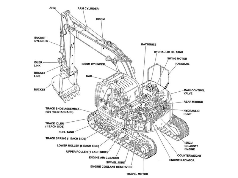
Track chains and sprockets wear as a pair. A stretched chain wears sprocket teeth faster, and worn teeth chew up a new chain. Track adjusters let you fine-tune tension so the chain stays seated. Loose tension causes slap and derailment. Tight tension overloads the final drive. You can view an excavator undercarriage parts diagram to see how these pieces connect, but the diagram shows layout, not wear. Noise, heat, and uneven tread tell you something is wrong. They do not tell you which part failed. A technician confirms that.
Parts of the Undercarriage System: A Care Guide
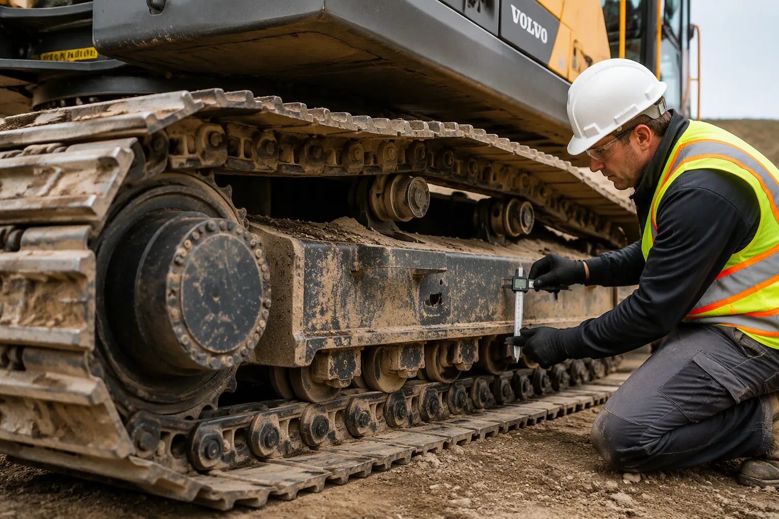
Measure condition using the actual undercarriage service procedure and compare it with the specified wear limits. Do not move track components side to side as a general maintenance rule. Isolate and securely support the machine as prescribed, and have trained personnel manage stored energy and service work.
Common Wear Problems and Inspection
Wear patterns can suggest areas to investigate, but they do not alone distinguish normal wear from misalignment. Use measured condition and qualified assessment.
Distinguishing check | Possible wear findings; verify by measurement | Possible alignment findings; verify by assessment |
|---|---|---|
Chain pitch / sprocket contact | Measure pitch or other specified wear dimensions using the actual procedure | One-sided engagement warrants an alignment and component-condition check |
Track path and guidance | Assess bushing and rail condition against the applicable service limits | Investigate guide, roller, idler and frame alignment rather than assuming a single cause |
Component condition | Use the specified measurement span, setup and acceptance limits | Bent shoes, frame damage, seized rollers, worn roller flanges, damaged track guards, or idler misalignment. |
Operating symptoms | Noise, vibration or abnormal movement warrants further investigation | Constant side loading, unstable tracking, unusual heat or seizure in rollers or idlers, and chain climbing mostly on one side. |
Verification method | Use the exact model’s operation and maintenance manual; measure several chain sections and compare sprocket tooth shape. | Compare left and right undercarriages; inspect polished contact paths, roller flanges, idler alignment, and guard contact; escalate to a full undercarriage wear report if needed. |
Rough engagement, abnormal travel or uneven wear can have several causes. Obtain measurements and qualified assessment before choosing replacement components.
Use the applicable manual’s measurement tools, setup, span and wear limits. Keep clear of moving tracks and pinch points. Do not assume a universal link count or that swapping assemblies corrects wear.
Track Tensioning and Replacement Signs
Measure and adjust track sag using the exact manual’s setup, measurement point and service limits. Do not assume a universal midpoint. Unexpected wear or movement requires diagnosis of the actual track system.
Volvo Excavator Undercarriage Parts: Practical FAQs
Operator Checks and Qualified Service
Operators should perform only the checks within the applicable manual and their training. Record visible damage or wear and arrange qualified assessment against the actual service limits. Tooth shape or a flat spot alone is not a universal replacement rule.
Operational checks must follow the approved procedure in a safe area with qualified personnel where required. Unequal travel can have several causes and does not alone prove alignment trouble. Catalog drawings identify layout, not condition.
Track Tension and Safety
Track adjustment and recoil assemblies can contain hazardous stored energy, including pressurized grease and spring forces. Do not loosen, dismantle or adjust them using a general article. Follow the exact service procedure with trained personnel and the required protective arrangements.
Use the prescribed shutdown, isolation, attachment support and lifting arrangements for the planned work. A hydraulic control lock is not a substitute for the approved energy-control procedure or secure mechanical support. Keep clear of raised components and moving tracks.
Inspect the undercarriage as an interconnected system using the actual service schedule and limits. Record findings and obtain qualified diagnosis for abnormal conditions. Verify machine and component identification, ordering numbers and specifications before purchasing replacements.
FAQ
How do you measure track chain wear?
Use the manual’s specified tools, setup, measurement span and wear limits. Qualified personnel should determine the replacement scope from the actual measured condition and related component inspection.
Why does one track wear faster than the other side?
Operating conditions, loading, alignment and component condition can contribute to uneven wear. Investigate the actual cause rather than assuming turning bias or swapping tracks is the remedy.
Should you replace undercarriage parts in pairs?
Inspect related parts together. Replace individual components or a group according to measured condition, compatibility and the applicable service instructions; a pair or full set is not a universal requirement.
What does a seized track roller look like?
Failure to rotate, abnormal running-surface wear, leakage or noise can warrant inspection. Check safely using the prescribed procedure and compare findings with the actual service limits before selecting a repair.
How do you verify replacement parts fit your machine?
Check the model, serial number, and part number against your machine’s specification. Confirm track pitch and track shoe width with your supplier. Quality management certification does not guarantee product fitment. Fitment verification requires the correct replacement parts and track measurements for your undercarriage system.
For Volvo excavator parts sourcing, consider YNF Machinery. Provide full machine and component identification, applicable part numbers and quantities, and request supported compatibility information, an actual quotation and written warranty and return terms before ordering.